Description
Description:
The Nokia 5110 is a basic graphic LCD screen for lots of applications. It was originally intended for as a cell phone screen. This one is mounted on an easy to solder PCB.
It uses the PCD8544 controller, which is the same used in the Nokia 3310 LCD. The PCD8544 is a low power CMOS LCD controller/driver, designed to drive a graphic display of 48 rows and 84 columns. All necessary functions for the display are provided in a single chip, including on-chip generation of LCD supply and bias voltages, resulting in a minimum of external components and low power consumption. The PCD8544 interfaces to microcontrollers through a serial bus interface.
Module Features.
*Resolution: 48 x 84 dot matrix panel.
*Power supply: 3.3V.
*Interface: SPI.
*Driver IC: PCD8544
Applications:
*This display is made of 84×48 individual pixels, so you can use it for graphics, text or bitmaps
How to get started using Nokia 5110 LCD display
These 84 by 48 pixel black and white LCDs are what you might be found in an old Nokia 3310. They’re not flash, and they don’t have a lot of display real-estate. But they are easy to control. If you’re looking to step up your project’s with user interface (UI) game from simple displays or LEDs, this graphic LCD is a good place to start.
Required materials:
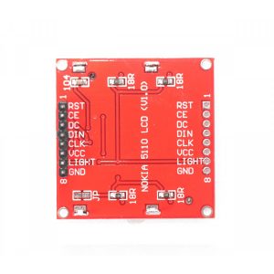
before we display our first image and real time sensor values on this LCD, let look at the pinout for this LCD, To interface with Arduino and power the graphic LCD, there are two, parallel 8-pin headers above and below it, flipping the board over, you will find the labels for each of the pins.
- RST: Reset pin
- CE : Chip Select
- DC: Mode Select
- VCC: Positive power supply
- CLK: Serial clock
- DN: Serial data in
- LIGHT:LED backlight supply
- GND: Ground
- Power Supply
To supply voltages on the LCD,the most important supply voltage — VCC — which supplies the logic circuits inside the LCD. The datasheet sates this should be between 2.7 and 3.3v. in normal state, the LCD will consume about 6 or 7mA
- Baclklight
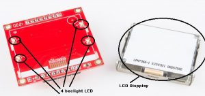
3.3V is required for LED back-lights on the board. if you were to remove the LCD from the PCB (not that you should, or need to), you’d see that these are back-lights in their simplest form- four white LEDs spaced around the edges of the board. You may also notice that there aren’t connected to any current limiting resistors.
This means you have to be careful with the voltage supply, either stick a current limiting resistor in series with the LED pin (as we did), or limit the supply to 3.3V max. The LED can pull a lot of current! with nothing to limit them, they’ll pull about 100mA at 3.3V
The control interface
Built into this LCD is a Philips PCD8544 display controller, which converts the massive parallel interface of the raw LCD to a more convenient serial one. The PCD8544 is controlled through a synchronous serial interface similar to SPI. there are clock(CLK) and data(DIN) input lines, and an active-low chip select(SCE) input as well On top of those three serial lines, there another input -DC-which tells the display whether the data it’s receiving is a command or displayable data.
Hardware Assembly and hookup
Before uploading code and sending data to the display, let’s take care of the hardware stuff first. that includes assembling the display, and hooking it up with arduino.
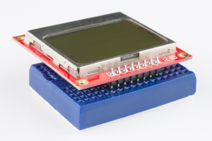
Assembly to “assemble” the LCD, you’ll need to solder something to one(or both) of the 8-pin header. there are plenty options available. to make the LCD breadboard-compatible, straight or right-angled male headers can be soldered in. otherwise, female to male jump wires can be used to connect it to the breadboard. below is LCD with straight male headers soldered in, plugged into a mini blue breadboard.
HookUp
In this example we’ll be connecting the LCD up to an Arduino UNO with a DHT11 temperature and humidity sensor like on the below scheme.
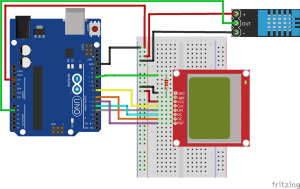
Pin connection:
- Arduino GND -> Nokia LCD GND
- D11 -> 330Ω -> LIGHT
- 5V -> VCC
- D8 -> CLK
- D4 -> DIN
- D5 -> DC
- D7 -> CE
- D6 -> RST
- 3.3V -> + Pin on DHT 11 sensor
- GND -> – Pin on DHT 11 sensor
- A1 -> OUT on DHT 11 sensor
Draw/Find/Modify a Bitmap
To begin, find a bitmap image that you’d like to print to the LCD. 84×48 monochrome pixels doesn’t give you a lot of room, but you can still get some fun stuff on there. Here are few examples:


Convert Bitmap to Array
The next step is converting that regular image file to a 504-byte array of char’s. There are a number of programs that can help with this around the web. We recommend LCD Assistant. To load up an image in LCD Assistant, go to File > Load Image. A preview of the image should open up, make sure it’s the right size – 84 pixels wide, 48 pixels tall. Also make sure the Byte orientation is set to Horizontal and the Size endianness is set to Little. The rest of the default settings (8 pixels/byte, etc.) should already be set correctly:
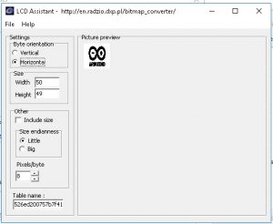
Then go to File > Save output to generate a temporary text file. Open that text file to have a look at your shiny new array. You’ll need to modify the type of the array to be just a char (not unsigned or const) Also make sure the array has the proper naming conventions (no dashes, don’t start with a number, etc.).
Import into the Sketch and Draw!
With that array created, copy the entire table over to your Arduino sketch. Use the same sketch from Example 1
LCD Demo
here is a sketch full of sample LCD control code. this small novella of the sketch shows off an array of graphics driver functions, character drawing tools, and other useful functions to help you get started using the LCD. Download the sketch (example sketch)
Resources
Bitmap tool: LCDAssistant
Arduino Libraries and code:
- u8glib_arduino_v1.17
- DHT11 sensor library
- Example code