Description
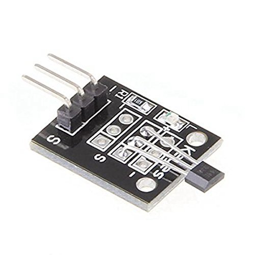
This module is used to detect the presence of magnetic. Whenever, it will be placed in the region of magnetic field then it will detect it and will give us the output. The module consists of a hall sensor which detects the presence of magnetic field.This module can be used in many projects like making a door alarm in which whenever the door will close, the magnetic will come near to the module, so it will detect the magnet.
Hall Sensor Module for Arduino
1. Non-Contact Switch
2. Hall Switch Integrated Circuit Using hall Effect Principle,
3. USES The Semiconductor Integrated Technology Manufacturing Magnetic Susceptibility of the Circuit,
4. It is by the Voltage Regulator, Hall Voltage Generator, Differential Amplifier, Schmidt Triggers, Temperature Compensation and the Open Collector Output Stage Circuit Composed of Magnetic Sensitive Sensor Circuit
5. Its Input For the Magnetic Induction Intensity, the Output is a Digital Voltage Signal
Getting started with the Hall Sensor Module for Arduino
For today’s tutorial, we will demonstrate how the hall effect sensor works by connecting it alongside a LED to an Arduino. The Arduino will be programmed such that when a magnet is brought close to the hall effect sensor, the LED comes on and when the magnet is removed, it goes off.
Hardware required
Connecting the Hardware

The connections for the hall sensor module are very easier. First connect the +5 v and ground pin of the sensor to the +5v and ground pin of the Arduino. Then connect the digital pin of the sensor to the pin 2 of the Arduino. We will use the pin 13 of the Arduino as the output pin which has a built in led attached to it on the Arduino board. So, whenever the magnet will be placed near the sensor, the module will detect the magnet and will turn on the led which is at the pin 13 of the Arduino. Through this way we can use this module in many other projects like making a door alarm and making a speedometer.
CODE
Copy the code and upload to your Arduino board. You should see the LED switch when a magnet is brought close to it
const int hallPin = 2 ; // initializing a pin for the sensor output
const int ledPin = 13 ; // initializing a pin for the led. Arduino has built in led attached to pin 13
// variables will change :
int hallState = 0 ; // initializing a variable for storing the status of the hall sensor.
void setup ( ) {
pinMode ( ledPin , OUTPUT ) ; // This will initialize the LED pin as an output pin :
pinMode ( hallPin , INPUT ) ; // This will initialize the hall effect sensor pin as an input pin to the Arduino :
Serial.begin( 9600 ) ;
Serial.println ( ” microcontrollerslab.com ” ) ;
Serial.println ( ” Testing the analog hall sensor module : ” ) ;
}
void loop ( ) {
hallState = digitalRead ( hallPin ) ; // reading from the sensor and storing the state of the hall effect sensor :
if ( hallState == LOW ) { // Checking whether the state of the module is high or low
Serial.println ( ” The state of the analog hall module is high ” ) ;
digitalWrite ( ledPin , HIGH ) ; // turn on the LED if he state of the module is high
}
else {
digitalWrite ( ledPin , LOW ) ; // otherwise turn off the LED :
Serial.println ( ” The state of the analog hall module is low ” ) ;
}
}
NOTE: IF you get stray ‘223’ errors The problem is with your “ and ” characters. Replace them with ordinary quotes, ", and you should be fine.
Working of Code
In the code, we have declared the pin 12 for sensor output and pin 13 for the led. The Arduino has a led attached at the pin 13. Then we checked the state of the sensor by using the digitalread command and applied the condition that if the state of the analog sensor module is high, then turn high the led and show on the serial monitor that the state of the analog sensor is high and of the state of the module is low, then turn low the led and show on the serial monitor that the state of the analog hall module is low.


