Description
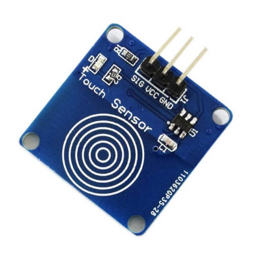
Digital Capacitive Touch Switch Module is based on TTP223B. Normally, it outputs low and keeps at low power state. When a touch is sensed on the circular marked region, it outputs high and switches to the quick response state. When not being touched for 12 seconds, it switches to low power state again.
Touch Sensor Interface :
- Control Interface: A total of three pins (GND, VCC, SIG), GND to the ground, VCC is the power supply, SIG digital signal output pin
- Power Indicator: Green LED, power on the right that is shiny
- Touch area: Similar to a fingerprint icon inside the area, you can touch the trigger finger.
- Positioning holes: 4 M2 screws positioning hole diameter is 2.2mm, the positioning of the module is easy to install, to achieve inter-module combination.
SPECIFICATION
| Operating Voltage(VDC) | 2 to 5.5 |
| Output high VOH | 0.8VCC V |
| Output low VOL | 0.3VCC V |
| Response time (touch mode) | 60 mS |
| Response time (low power mode) | 220 mS |
| Length (mm) | 24 |
| Width (mm) | 24 |
| Height (mm) | 2 |
| Weight (gm) | 0.6 |
Features :
- Low power consumption
- Power supply for 2 ~ 5.5V DC
- Can replace the traditional touch of a button
- Four M2 screws positioning holes for easy installation
- Output Pin Sink Current (@ VCC = 3V, VOL = 0.6V) : 8 mA
- Output pin pull-up current (@ VCC = 3V, VOH = 2.4V) : 4 mA
Getting started with the TTP223B Digital Touch Sensor Capacitive
This example shows below an output to your serial monitor indicating whether or not the sensor is pressed or touched.
Hardware required
- Arduino Uno
- Digital Touch sensor
- Jumper wires
Connecting the Hardware
This is a real simple set up. You will know that you have power properly applied when the green LED is on.

Upload the sample sketch
The sketch below provides an output to your serial monitor indicating whether or not the sensor is pressed.
// Capacitive Touch Sensor Tutorial
// When Sig Output is high, touch sensor is being pressed
#define ctsPin 2 // Pin for capactitive touch sensor
int ledPin = 13; // pin for the LED
void setup() {
Serial.begin(9600);
pinMode(ledPin, OUTPUT);
pinMode(ctsPin, INPUT);
}
void loop() {
int ctsValue = digitalRead(ctsPin);
if (ctsValue == HIGH){
digitalWrite(ledPin, HIGH);
Serial.println(“TOUCHED”);
}
else{
digitalWrite(ledPin,LOW);
Serial.println(“not touched”);
}
delay(500);
}
Testing the circuit
Once you’ve uploaded the sketch, open your serial monitor. Touch the sensor pad while looking at the monitor. You should see an output that looks something like the picture below.


